OpenLab 2014/07 | Hands on Arduino
- Date: 31. 10. 2014 && 11.3.2016
- Workshop by: Lukáš Němec
- Cake: we will see…
What to expect
Introduction to microcontroller programming focused mainly on Arduino platform. We will start with basics, what to expect from Arduino and what is Arduino capable of with some examples. Then theoretic part, how to connect everything together and mainly how to write programs. Thus everything from using basic C skills to Arduino-specific functions.
As we learn enough of theoretic background, you will get your hands on Arduino boards and you will have a chance to program your own blinking LED or something similar, depending on your time, skill and enthusiasm.
What to prepare
- Arduino IDE (download, optionally install) - more info here: http://arduino.cc/en/Main/Software
- Ideas what to do, some inspiration can be found here:
- Arduino tutorials (also can be found in IDE) http://arduino.cc/en/Tutorial/HomePage
- Makezine youTube playlist: https://www.youtube.com/playlist?list=PLE0C08A11B1164932
- Google and own imagination
")
There will be a supply of LEDs, resistors, some sensors (light, temperature, IR …) and a bunch of other Arduino related stuff.
Arduino Theory
Arduino Ecosystem
Arduino is a phenomenon of last few years, quickly gaining popularity in many fields. It originated somewhere in DIY community as easily manageable microcontroller with Open-Source design, that was accessible to everyone. With this huge success, a family of official Arduino board quickly grew, as well as all other products, that were somehow Arduino related.
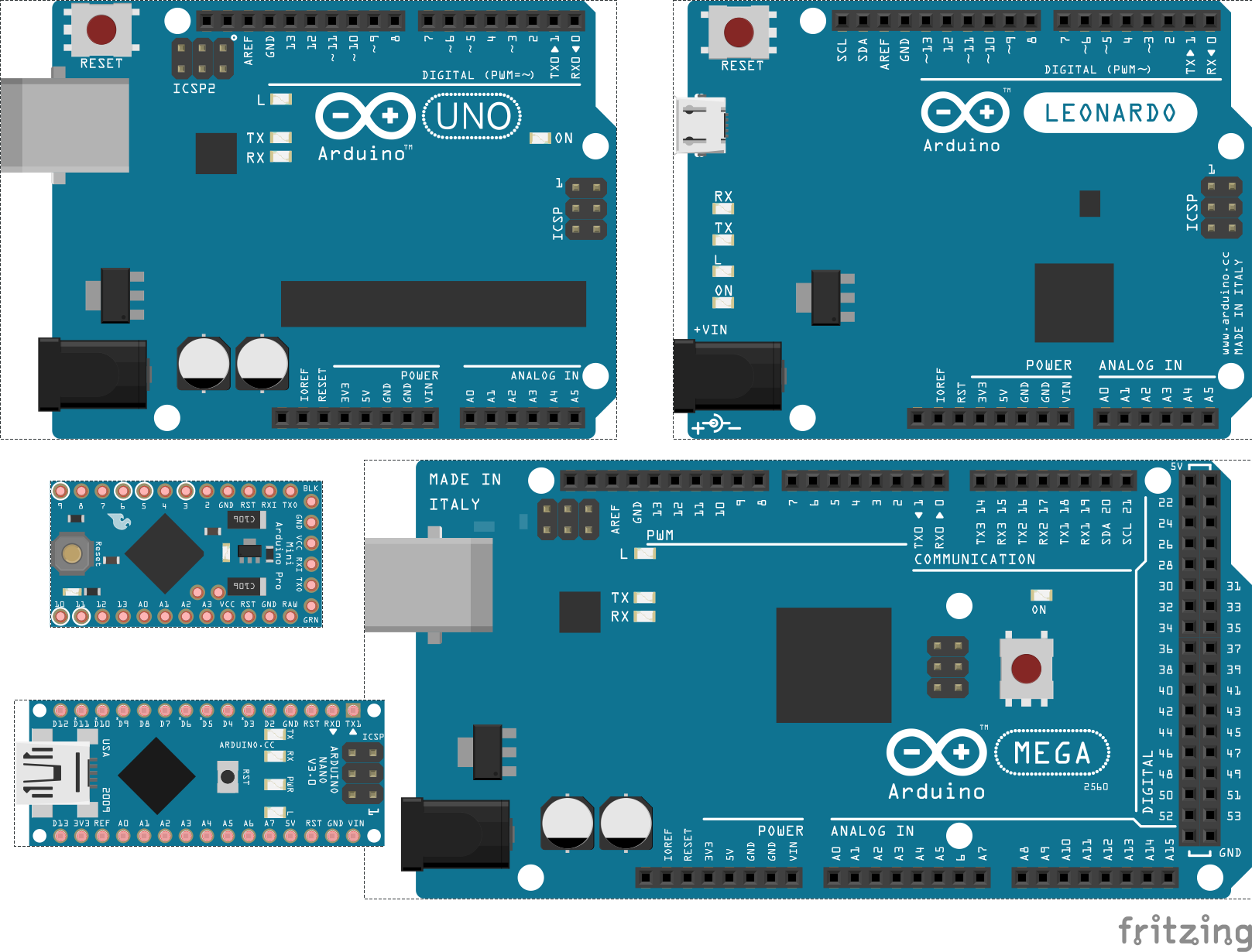
Today There is huge selection of boards, starting from basic UNO, a little bit more advanced Leonardo, up to Arduino MEGA. On the other side, if you are interested in smaller sizes, there is Arduino micro, mini and nano, some that small, that there is no space for USB connectivity. Also, if you want to keep up with the latest development, you can try out Arduino Yún or soon to come Arduino Tre. There is also market for special purpose microcontrollers, like wearable electronics, which can be designed using Arduino LillyPad and conductive thread.
Also open source design of Arduino is by many viewed as the perfect point to start with own modifications, for example, Jeenodes - Arduino based WSN modules. Also, there is wide range of unofficial boards, that just take open source design, and sell it under different name with cheaper price (Funduino, Robotino etc. usually called Arduino compatible HW)
Concerning accessories, there are many shields, which can add specific functionality to your Arduino, for example, GSM of WIFI shields. These become useful when you are building a diet control machine, that will publish tweet every time you open a door to your fridge. Also, there is a wide range of sensors, so you can measure almost everything, from light and humidity to methane concentration.
How to connect everything together
Every Arduino has pins, usually with other sockets, but you can also buy just bare PCBs and make sothering yourself if you ever need to do so. There are three basic categories of pins: analog, digital and power + some special purpose ones. Pins are usually numbered or labeled, and you can see these directly on the board.
Digital pins
Use digital signal, thus input and output has only two possible values. These are 1 and 0, or in practical view, 5V or nothing. Digital pins can be also used to read data, but again only two states, so ideal choice for switches. To make things little bit more tricky, some digital pins have pulse-width modulation (PWM) enabled and these are usually labelled with ∼. These pins can be used for analog write commands, in other way, output can be set anywhere between 0 and 255. These can be used for a dimmer or precise positioning of servo motors.
Analog pins
Analog pins are used for analog read when we need more precise value than just binary 0 or 1. The output from these pins can be anything between 0 to 1023 and we use these pins for reading values from sensors, e.g. humidity, light, distance etc.
Power and special pins
The last category of pins are power pins, these are ground pins, 5V, and 3.5V pins. Connect these to power breadboard power lines or components directly, as needed.
All other pins are used for special purposes, like reset pin or in a case of smaller or older versions of Arduino for actual programming (USB interface is not present).
<note important>Reset pin is usually present also in form of a button on board, this can be used for reinitializing state of your code back to setup function.</note>
How to upload code
Recommended steps:
- Connect Arduino to PC, usually USB cable type B, or micro USB with new boards.
- Start Arduino IDE
- Select Tools - Board Type (mostly Arduino UNO)
- Select Tools - Serial Port (there will be usually only one when only one Arduino board is connected)
- Write your code or open some example sketches (or load some saved sketches)
- Do all the wiring (can be done as the first step or as last)
- Press Ctrl + R to compile
- Press Ctrl + U to upload code to your Arduino
- Optionally repeat while fixing bugs or adding features (two names for the same thing)
Arduino code basics
Programming for arduino is basically C language with some specific commands and libraries.
Introduction
Smallest code, that sucessfully compiles looks like this:
void setup() {
}

void loop() {
}
Here you have two functions, one for initial setup of variables, pins etc, and loop function that runs in infinite loop after setup as it's name suggests.
Blinking LED
Now for some code, that actually does something useful (blinking LED):
//global constant for more comprehensible code, you can use just number,
//this way it is just more user-friendly when handling multiple pins
int ledPin = 13;

void setup() {
  // initialize digital pin 13 as an output, LED will be connected here
  pinMode(ledPin, OUTPUT);
}

void loop() {
  //digitalWrite(pin, value) command is used to set voltageon pin to certain value
  //most usefull are constants HIGH and LOW, you don't need to use numbers
  digitalWrite(ledPin, HIGH);   // turn the LED on (HIGH is the voltage level)
  delay(1000);              // wait for a second, led is turned on
  digitalWrite(ledPin, LOW);    // turn the LED off by making the voltage LOW
  delay(1000);              // wait for a second, led is turned off
}
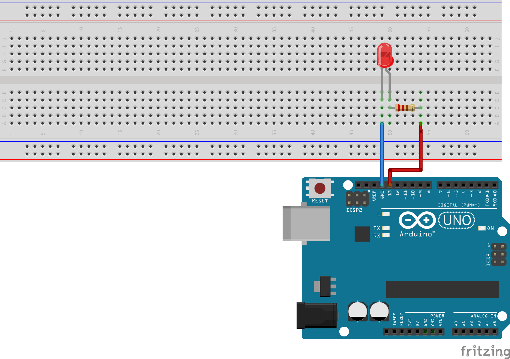
This code also requires some basic assembly, LED needs to be connected to Arduino, it is recommended to use a breadboard and some jumper wires, an exact way is illustrated on the image below.
<note important>When connecting LED, remember that LEDs are like all other diodes, so electricity flows in one direction only. The longer lead is positive (anode) needs to be connected to power and shorter leg (cathode) to ground.</note> <note warning>LEDs are not capable of handling Arduino's 5V power, so resistor is required. Usually one which has 220Ω is used, but in this case it is not necessary to be exact, so you can use 200Ω or 300Ω as well and it will slightly affect brightness of LED, but nothing more. Generally more resistance does no harm, less resistance could burn the LED.</note>
Sensors, Analog input and Serial monitor
Next example will show, how to read values from sensors and how to obtain debugging information from Arduino board.
In order to receive value from sensor, we have to use analog input pins (Arduino UNO has range from A0 to A5) and read values with analogRead function. There are many possibilities what to use as a source of input, you can choose from whatever is available, rotary potentiometer, light resistor (changes resistivity based on light) or any other option you choose.
Every sensor (save the more complicated ones) has basically three connections, power (Arduino's 5V), ground and output. The output is connected to the analog input pin, in the case of an image below, two options are illustrated, one light resistor (with another 10KΩ resistor for better results) and one rotary potentiometer, both produce analog values from 0 to 1023 while reading with analogRead function.
Next is serial output, which can be used either for debugging or logging values. Output needs to be initialized in setup phase with following Serial.begin(9600); where 9600 means frequency in bauds. Then you can use Serial.println(“text”); anywhere in code. This messages can be captured, if you open Serial monitor from IDE (shortcut CTRL+Shift+M) and select same frequency as previously.
int sensorPin = A0;    // select the input pin for the potentiometer
int sensorValue = 0;  // variable to store the value

void setup() {
  //initialize both pin and Serial
  pinMode(sensorPin, INPUT);
  Serial.begin(9600);
}

void loop() {
  // read the value
  sensorValue = analogRead(sensorPin);
  //print value on serial
  Serial.println(sensorValue);
  //wait
  delay(1000);
}
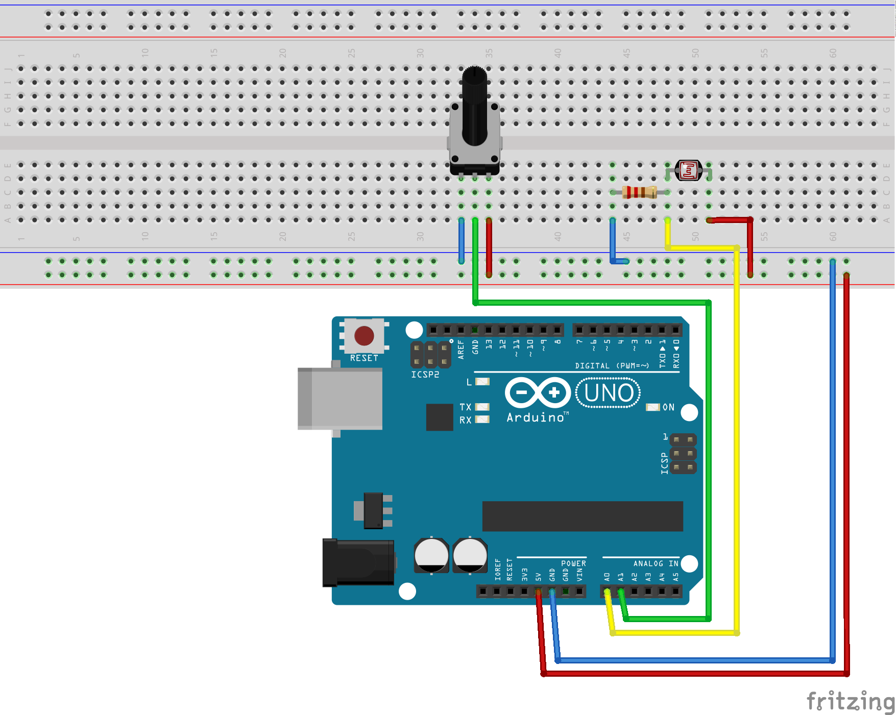 <note important>Image shows two possible options, connected to pins A0 and A1, code shows reading input only from A0.</note>
How to continue
Ideas, where to get them
As stated previously, the idea is begining of everything, thus, you need ideas what to do with Arduino. Hopefully, you can come up with many of your own, but if you need some inspiration boost, following might help:
- Arduino Started Kit (book of 15 tutorials together with Arduino board and parts you will need)
- Other official Arduino Examples and already finished projects http://arduino.cc/
- Makezine videos, or paper issue: http://makezine.com/category/electronics/arduino/
- many other, just search for “Arduino Ideas”
What to buy
You will need something to start with, either you already have some electronics, and you just need ome jump start into it, or you are starting from scratch. Either way, there are many ways to spend your budget, so here comes a list of essential parts and tools and also a list of nice things to have, but which you can do without.
Essential
- Arduino Board
- some basic electronic parts (LEDs, resistors)
- breadboard
- jumper wires
Nice to have
- variety of sensors
- All other usefull parts (depending on project this can be servo motors of Liquid crystal display etc.)
- multimeter
- sothering iron (when you want to make project permanent)
- more Arduino boards (more projects at once becomes easier)
Where to buy
- Official Arduino strore - arduino.cc, based in Italy, sells Arduino boards, shields, sensors
- GM electronics - gme.cz, overpriced Arduinos, but nice for small parts like LEDs, based in Brno, so ideal if you are missing just one part to complete project
- dealExreme.com - dx.com, china based, cheap, not original Arduinos, but Funduinos etc. (so called Arduino compatible parts), takes about 4 weeks to arrive, ideal for stocking up on parts of budget buys of boards
JeeNodes
Jeenodes are special purpose boards (Arduino based) for WSN networks. Because of these facts, there is a limited number of pins and some other limitations, but for our cause they will be more than sufficient and only a few changes have to be made.
First connections, following image, shows how to connect JeeNode, LED and resistor together, especially which ports to use, since they are not as nicely labeled as other Arduino boards.

And now the other part, small change in source code:
//pin placement is changed to 4
int ledPin = 4;

void setup() {
  pinMode(ledPin, OUTPUT);
}

void loop() {
  digitalWrite(ledPin, HIGH);
  delay(1000);
  digitalWrite(ledPin, LOW);
  delay(1000);
}
Other projects are changed acordingly.